



 The Specifier is an MCAD tool for specifying structural-assemblies.
A structural-assembly is specified in terms of it's component parts and construction processes for connecting these parts. These processes can be implemented in an associated production facility called a Unit-construction-hub, also specified using The Specifier.
The Specifier is an MCAD tool for specifying structural-assemblies.
A structural-assembly is specified in terms of it's component parts and construction processes for connecting these parts. These processes can be implemented in an associated production facility called a Unit-construction-hub, also specified using The Specifier.

Efficient control
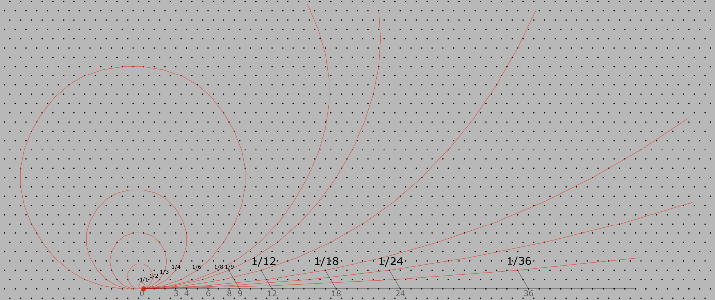 Curves rendered on a hex-grid using integral ratio identifiers.
The Specifier uses a hexagonal-grid as a basis for spatial representation.
This simplifies the specification of 3D objects and their spatial associations.
Existing tools do not use a grid for spatial representation.
This makes the specification of curves and 3D surfaces complicated.
The Specifier is designed for efficient control over curve and surface specification.
Development roadmap
- Current status
We are in the process of creating a first prototype. This prototype will demonstrate the specification process for a bicycle-wheel and then a bicycle-stabilizer structural assembly. - Plans
- Create specifications for past land-vehicle design modifications using the tool.
- Create distributable apps for MacOS, Windows and Linux.
- Create a version of the app for an iPhone-based laptop platform.
Design approach
In addition to its use of a hex-grid, and a targeted usage domain, The Specifier's design approach has the following aspects.
Use-centric design The Specifier is being designed in sync with the design of a bicycle-stabiliser. The design approach is not to design everything up-front for the most general design scenario, but instead design for a specific use-case, then redesign for more use-cases, then identify those tool aspects that are common across use-cases and add them to a more general-purpose tool. We refer to this as use-centric design.
Simplicity The Specifier uses a simpler UI-design paradigm (InterUnit-UI) than the commonly used WIMP paradigm. InterUnit-UI is Khitchdee Design's new UI-design paradigm that has far better ergonomics than WIMP.

Most existing tools have poor usage-ergonomics. They are all apps running inside WIMP-based UI frameworks (native or browser-based). They tend to be feature heavy, require a lot of fine-grained mouse usage and switching between mouse and keyboard use, and hence require the designer to be attentive to the app's UI to a large degree. Shapr3D is a recent tool that targets better usage-ergonomics.
Some ergonomic modelling Includes some ergonomic modeling of the user of the design. This is a neccesary part of the specification of any structural-assembly that will be used by a human user. It also helps in the description of a construction process.
Hardware friendly
The Specifier includes a specially designed hex-grid based 3D graphics library.
This library does not rely on 3D hardware acceleration,
and is implemented, instead, using a platform's native 2D drawing library.
It is also designed with a minimal feature-set and resource usage approach.
These implementation choices significantly lower computational complexity,
and The Specifier will be very responsive on average PC hardware as a native app.
All existing tools have high implementation complexity and are either implemented as native apps,
requiring workstation class processors,
or cloud-based apps, implying browser and internet-bandwidth constraints.
Licensing
Khitchdee Design ( ) plans to license The Specifier to industrial-designers and prototype developers.
We also plan to license the Specifier's hex-grid based geometry modeller to other CAD tool developers.
) plans to license The Specifier to industrial-designers and prototype developers.
We also plan to license the Specifier's hex-grid based geometry modeller to other CAD tool developers.
Additional Information
What is (3D) specification visualisation?
A (design-specification) Visualiser implements perspective-correct display-screen mapping of modelled 3D objects.
Our visualiser models a camera with a location and orientation,
and a single light source, at the same orientation and location as the camera.
We represent a 3D object as its outer surface, a lattice of 3D planar segments.
These 3D planar segments are described very simply on a hex-grid.
We map these 3D planar segments onto a 2D screen using 4-point plane-mapping.
A curved plane (in 3D) is modelled as a lattice of flat hex-grid planes.
Our visualiser uses only the device's (2D) drawing engine,
and targets a visualisation time of 100ms/frame
for a bicycle-model at 4K resolution on an Snapdragon 8 Gen 5 SOC class device.
What is design-specification?
There are 2 aspects to the specification of a land-vehicle design.
-
A structural specification:
A static description of the built up structure of a design. It includes a specification of each part in a design, how the parts connect with each other, and a structural model of the user (if applicable). -
A construction-process specification:
Specifies the construction-process of a design. How each component in the design is contructed and how the components are put together to produce the design. This is useful for an assembler or a fabricator.
Construction-process specification in the Specifier (planned) We plan to produce a construction-processes specification component after the structural specification component. The designer will identify several construction states in the construction process. Each construction state will be a physical model of the relative placement of the components and tools in the process. The designer will indicate transitions between construction states. The construction-process specifier will use these construction states and transitions between them to create an interpolated sequence of models to be visualised. This sequence will be visualised using the Visualiser with some animation controls.
Photograph assisted specification in the Specifier (planned) After the mouse and keyboard specification interface, we plan to produce an additional interface to improve structural specification input efficiency. This interface will work as follows:
- A designer loads photographs of a real object into the app (with a description of the approximate camera parameters used in taking those photographs).
- Identifies (in terms of 2D point descriptions) the components in the structure of the object in the photograph.
- For each component, they describe its 3D orientation and size, based on physical measurements.